Welcome to Safety Test Switch
ST Switch
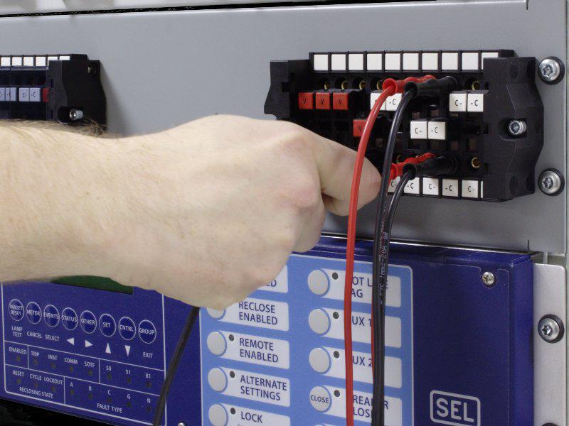
The ST Switch is a test block for interfacing substation devices (protection relays, fault recorders, revenue meters, ... ) to the voltage and current transformers and to other equipment on the system side of a power grid.
The ST Switch uses disconnect pins to isolate the substation devices from the system side equipment. Once isolated, secondary injection can be performed using banana jacks on the front side of the test block.
The design is such that an operator can easily see whether the internal contacts are open or closed.
Key Features
| Finger-safe There are no exposed metallic parts on the ST Switch, greatly increasing safety during testing. |
|
| Keyed Disconnect Pins Disconnect pins are keyed to the corresponding slots of the test block, preventing mistakes and errors during test. |
|
| Integrated Status Window A status window at the front indicates whether the internal contacts are open or closed. |
|
| Cabling Connections Cabling connections are replicated from the FT Switch and offer maximum convenience for technicians and enigneers. |
|
| Less Than 2 mO Internal Resistance Thanks to the patented construction, ST Switches have an extremely low internal resistance. This decreases the burden placed on instrumentation transformers and also reduces heat dissipation inside cabinets and panels. |
|
| Over 100 Models and Counting Models with 8, 10, 12, 14, 16, 18 or 20 poles. Any combination of currents, voltages or trip signals. Custom labeling. The right ST Switch either already exists or can easily be created. |
|
| Ideal for Retrofit of Older FT Switches The 10-pole models use the same panel cutout as the older FT switches. Even the terminal labeling is the same. That means that you can have the increased safety and efficiency from the ST Switch without having to change your engineering drawings. |
Principle of Operation
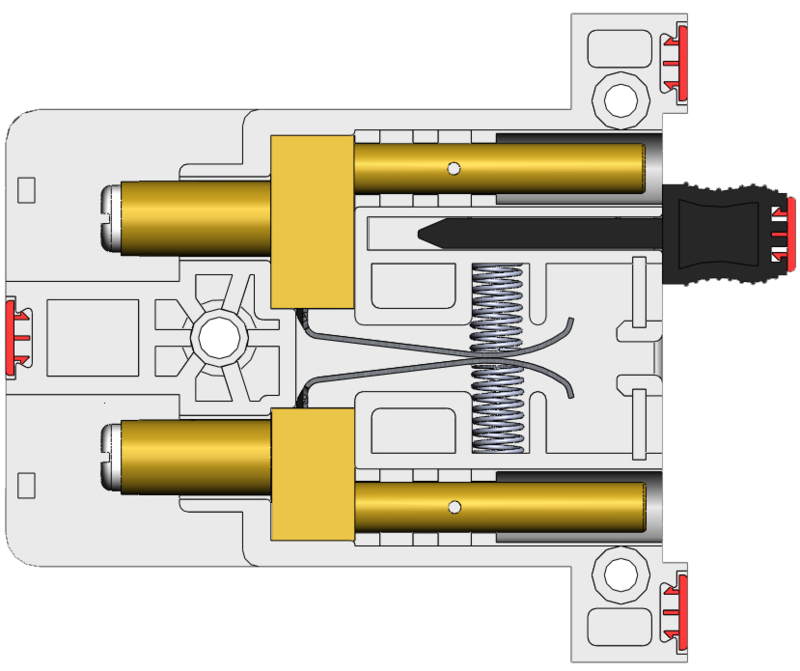 |
Closed Circuit An ST Switch contains 8, 10, 12, 14, 16, 18 or 20 modular units (or poles) each allocated to a current, voltage, signal or trip circuit. Each circuit is connected through the block via two silver-plated copper contacts, pressed securely together by two pressure springs to create a highly conductive electrical connection. In this situation, a electrical connection is established between the device side (B) and the system side (A). |
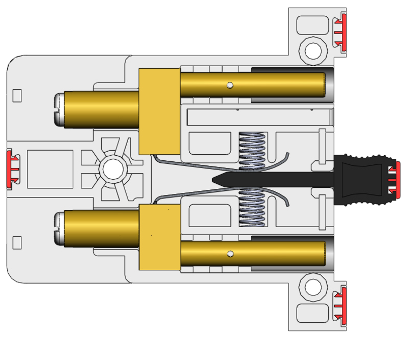 |
Open Circuit To open one of these modular poles, a disconnect pin is removed from its inactive "parking" position and inserted between the silver-coated copper contacts (the "test" position). In this position, the device and system sides of the test block are isolated from each other. For current circuits, the disconnect pins include internal shorting bridges. When the pin is moved back to the "parking" position, the internal springs force the contacts back together, returning the circuit to its normally-closed position. There is no in-between position, completely eliminating the risk of accidents resulting from improperly closed circuits. |